

This article is a translated reproduction from Les Grandes Usines: Études Industrielles en France et à l’Étranger, authored by Turgan in 1868. Turgan, a notable French engineer and writer, meticulously documented industrial advancements and factory operations across France and beyond, offering a rare glimpse into the technical and economic landscape of the 19th century. In this excerpt, we explore the pioneering work of Eugène Lefaucheux’s arms factory, a beacon of innovation in firearm manufacturing during that era.
Except for state-owned factories, there are no large gun-making factories in France. There are many assembly workshops, but barrels are generally made in special establishments, and the lock parts by scattered workers—most of these workers even come from Liège.
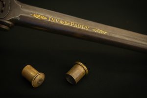
The only significant private industry establishment where weapons are manufactured in France using machine tools is of recent creation; it was founded by Mr. Eugène Lefaucheux, son of the famous gunsmith who gave his name to the break-action gun, loaded with cartridges with metallic bases.
The factory was created for the manufacture of revolver weapons, brought to a state of perfection that allows for industrial development.
In 1854, Mr. Eugène Lefaucheux resolved this issue by manufacturing a revolver in which it was possible to load multiple-shot weapons, functioning by rotation, with Lefaucheux cartridges, operating successively for each shot, and without the need to use a rod. These arrangements combine with the use of a fixed breech, used as a support point and with an additional mechanism allowing the ejection of the metallic cartridge if there were difficulties in removing it after discharge.
Examples of the M1854 from the Archives
Mr. Lefaucheux did not change anything in the design of the barrel and stock of the already known revolvers: the movement of the cylinder was still carried out by cocking the hammer and by a pawl acting on a hexagonal notch, just as the stop time of this cylinder was always obtained by means of six notches stopped by the head of a spring protruding by cocking the hammer. The cylinder bearing the chambers was pierced with six holes, plus a central opening for the rod around which the rotation took place; each barrel was hollowed out at its base to form a notch to allow the pin to pass, on which the hammer fell, just like the cartridge of Mr. Lefaucheux’s father.
Behind the cylinder was a breech in the shape of a half-sphere, also bearing a groove for the hammer fall, and on the side, a door opening for the introduction of cartridges, which were placed successively in each chamber by turning the cylinder by hand.
Laterally along the barrel and in a slide, there moved a slide intended to push back either the complete cartridge when one wanted to unload the weapon without using it, or the fragments of the cartridge and the base if they did not fall out by themselves.
This first project was modified a few months later by adding a new spring to keep the door covering the opening in the breech for the passage of cartridges for loading the chambers closed. A small round rod with a spring that held it in its sheath replaced the slide; even at that time, Mr. Lefaucheux intended to use center-fire cartridges in which the pin no longer served as a striker but as an anvil, and was attached to the bullet itself or the casing. These very new and ingenious arrangements formed the basis for Mr. Lefaucheux’s work, who, while manufacturing considerable quantities of weapons based on these primitive data, has continuously sought to perfect the revolver.
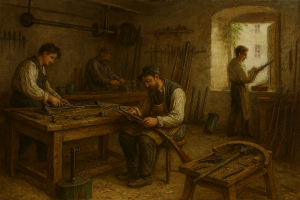
He could not apply his invention industrially, as Mr. Lefaucheux’s father, dedicating all the profits from his business to the advancement of gun-making, had left him nothing; assisted by some people, he began the production of the new revolver with a small capital, and soon he was able to create in Paris a workshop for the construction of weapons equipped with machine tools and applying modern mechanical tooling to gun-making, an industry so ingenious and persistent in its research but so traditional in its manufacturing methods.
When Mr. Lefaucheux wanted to expand his workshops to meet the demands, he found no more than seventy gun-makers in Paris; indeed, except for the so-called Paris barrels, all other barrels and almost all other parts of the weapon except the hammer come a bit from Saint-Etienne and much from Liège, and the workers in Paris are engaged not in manufacturing but in finishing and assembling the parts.
Mr. Lefaucheux submitted his invention to the Minister of the Navy, who appointed commissions and conducted experiments; the report from these commissions was favorable, and the Lefaucheux revolver was adopted as the standard armament for the Imperial Navy.
This adoption was imitated by the merchant navy and foreign governments: Italy, Russia, Germany, Sweden, and Egypt followed our government’s lead; the Paris workshops employed up to 475 workers and produced an average of 150 revolvers per day. The carbine of the same system was also manufactured successfully: finally, the annual turnover rose to 1,800,000 francs for an initial capital of 15,000 francs. Before describing the manufacture of the current revolver, which has been achieved after a series of modifications, we must summarize the previous and contemporary work on this issue.
While it is difficult to accurately trace the history of fulminating powders, it is much easier to follow the various modifications of weapons. Few subjects have seen more human mechanical ingenuity applied; one only needs to visit the Saint-Thomas d’Aquin Museum and the Tower of London to get an idea of the variety of inventions that have been applied to portable war or hunting weapons; hundreds of weapons and models of rifles, carbines, and pistols are counted. Many of these weapons show similarities in their main arrangements, some even seem to reinvent what our ancestors had discovered one or two centuries earlier.
However, from time to time in the history of weapons, certain distinct forms emerge that seem to summarize previous efforts, give substance to vague attempts, and characterize an era.
It was first an iron tube assembled for shooting with a box where powder was placed and then connected with iron bands and brackets. Breech-loading is thus the original method of loading firearms; the first improvement was to screw the box to the tube. For a time, these weapons were almost as dangerous to their users as to the enemy, so they were placed on fixed supports, and after being roughly aimed, the fire was only applied after moving away to a respectful distance, which was not an easy way to shoot accurately. Soon confidence increased, and a wooden handle was added, a hook or spike to fix the tube on a stand; later, the match was fitted in the jaws of a dog called a serpentine, a trigger brought the serpentine close to the pan, and the match ignited the fire; then came the musket and pistol called wheel-lock, with a dog carrying the stone, in which sparks were produced by the rotation friction of a steel wheel. The musket with a dog and pan replaced the wheel-lock musket and lasted a long time.
The percussion weapon, with a dog on a cap, otherwise known as a piston rifle, marks another such pause. The breech-loading weapon has just been adopted for the army; finally, the latest improvement, the repeating weapon, or revolver pistol and carbine that came from America and are used everywhere, are still little known in France. Between these various fundamental modifications, each embodied in a type followed by all nations, there are many attempts that have not led to any regular and industrial application and can only be found in museums.
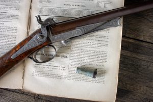
The percussion rifle remains without an author’s name, but it is not the same for the break-action hunting rifle, now called the Lefaucheux rifle worldwide, although it has long since fallen into the public domain. The Colt revolvers and, more recently, the Lefaucheux revolver present a set of typical arrangements that make them complete machines, functioning and operating; they are to ancient weapons with similar arrangements what Stephenson’s locomotive was to Papin’s boiler.
In the Saint-Thomas-d’Aquin Museum, there are several revolver weapons, but the cylinder that holds the chambers always moves by hand and not by a suitable mechanism; three of them are matchlocks, indicating they were made in the early seventeenth century: one is a small hunting arquebus with a barrel in flats, and the drum has eight chambers, the flash hole corresponding to each is closed by a sliding cover; a spring with a hook stops each chamber when the serpentine comes to light the fire. It bears the number 1251.
Number 1252 is a matchlock arquebus whose drum, containing five charges, rotates on an axis parallel to that of the barrel.
Number 1253 also has five chambers but only one pan, which is primed anew for each shot, while the previous number has a cover for each charge.
Number 1254 is a German musket from the mid-seventeenth century, with ignition by means of a wheel; it has three chambers rotating on an axis parallel to that of the barrel.
Number 1255 is a French flintlock rifle, with a drum and five shots, made in the eighteenth century; on the lock body is inscribed: Marchaux in Grenoble.
From the same period is another six-shot rifle marked 1256; finally, at number 1260 is a rifle by Elisha Collier, with five charges, whose drum turns by hand, held between two plates, the lower of which pushes the drum towards the barrel, and the upper plate closes the chambers. The rod used to load the breeches is placed in the stock; the lock carries a primer magazine placed in a drawer.
We reproduce, from a Colt brochure (a), some specimens of old revolving breech weapons:
The first, at the top of page 266, is supposed to belong to the tenth century and is in the arms museum of the Tower of London; its revolving breech with four chambers is mounted on a shaft parallel to it and fixed to the barrel of the weapon.
The rear end of this shaft is attached to the rifle stock by a transverse key pin; notches are made in a protrusion at the front part of the breech to receive the end of a spring fixed to the stock and which extends across the breech to hold it in place when one of these chambers is exactly aligned with the rifle barrel.
This piece appears to be of oriental origin; the lock is a matchlock.
Each of the breech chambers is equipped with a pan and a movable cover that must be pushed back with a finger before firing to put the powder in the pan in contact with the match. To proceed with a second discharge, the matchlock is pulled back, and the breech is turned by hand to present a second loaded chamber aligned with the barrel.
The figure below is also a matchlock. Mr. Colt saw it at Mr. Forsyth’s, to whom it had been given by Lord William Bentinck, Governor-General of India. The breech, which is turned by hand, has five chambers, each with a pan and a movable cover. The shaft is attached to the barrel, and the end touching the breech is larger to correspond with the diameter of the revolving chamber, serving somewhat as a protection or recoil piece. But to reduce the chances of the danger, undoubtedly feared, of simultaneous discharge of all the chambers due to the fire spreading from the firing chamber, which must have been the inevitable effect of this sort of fitting, the craftsman provided outlets for the charges by drilling holes through the larger part of the barrel, corresponding to the loading chambers of the revolving breech.
The third figure is a significantly improved weapon over the previous rifles. This weapon, found in the armory gallery of the Tower of London, has a flintlock with a wheel and only one common pan for all six chambers of the revolving breech: this pan has a sliding cover and is arranged so that a separate edge of a vertical wheel projects into the powder in the pan; this wheel receives rapid rotational movement by means of a detent spring acting on a lever attached to the wheel’s axle, whose teeth striking the stone generate the sparks that communicate the fire to the powder in the pan.
The fire is then communicated laterally to a powder train, about two and a half inches long, before reaching the charge in the breech, and this powder train, like the one in the pan, must be renewed each time before discharging the charges in the following chambers. A stop pin is made to enter the holes of the wheel to stop its action when desired; when it is removed, the trigger is pressed, and the shot is fired. In this sample, too, the breech is turned by hand, and the barrel and breech are brought into contact by means of a screw nut acting on the threaded end of the breech shaft. By using only one primer pan for all the chambers in the breech, and due to the apparent need to close the rear end of the breech with a recoil cap, leaving only a narrow opening for the passage of powder from the pan to the breech, the chances of simultaneous discharge of all the chambers were greatly increased; and this is because the cap covering the rear end of the breech prevents the fire from escaping laterally and forms a natural channel that directs the deflected fire to the light communication holes of all the other charges. This rifle does not have a stock in front of the breech; but unlike the previous samples, the barrel is notched and cut out on both sides, allowing the ball to escape in case of premature explosion.
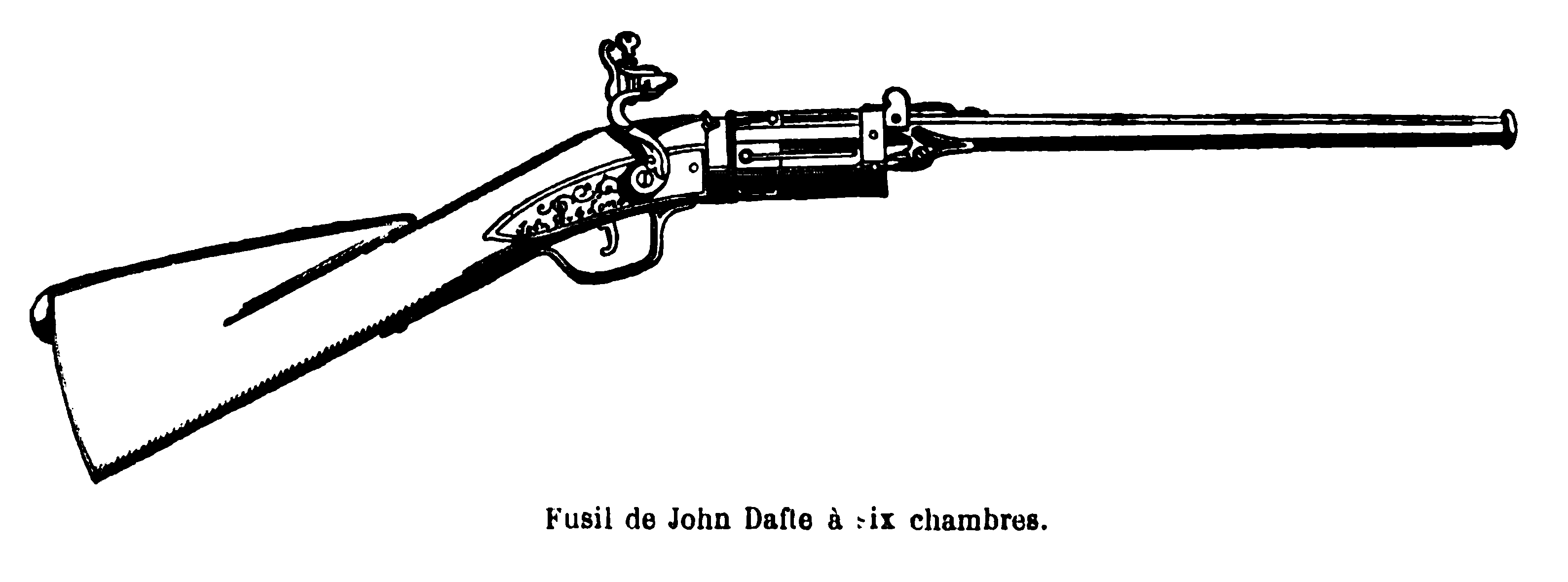
The fourth figure is a rifle by Jonhn Dafte, of London, with six chambers and bayonets set into the periphery of the breech.
The fifth figure, says Colonel Colt, shows the most recent example of a multi-chambered breech firearm, a flintlock example patented in 1818 in favor of Elisha H. Collier of the United States of America; it exhibits all the main defects of these ancient weapons, although these defects should have already been discovered by that time, and even the old gunsmiths had remedied them. The most defective parts of this weapon are the primer reservoir, the tube that should lead the fire to all the lights, and the cap in front of the breech, which should direct the fire laterally into the neighboring chambers.
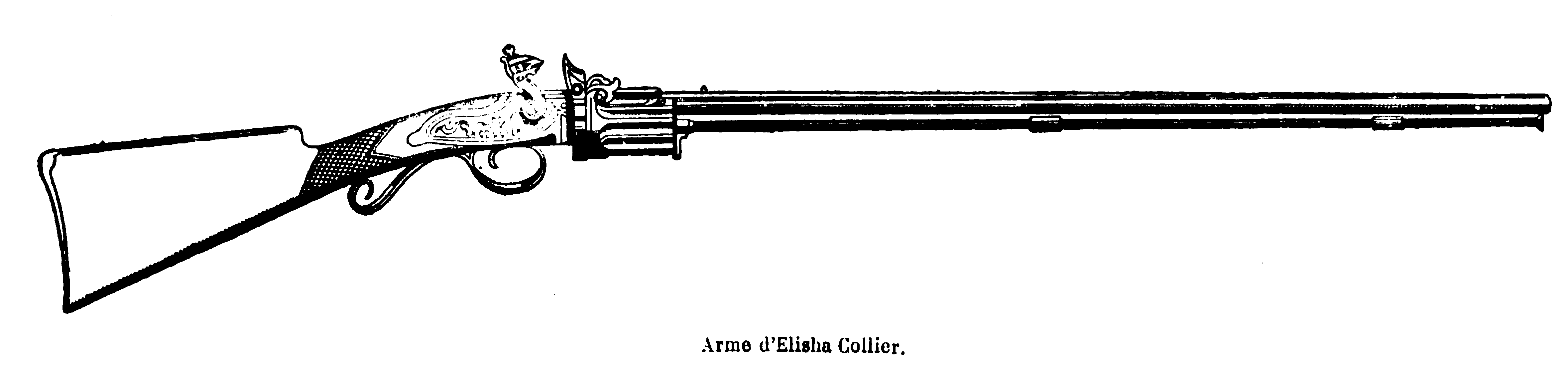
The breech is arranged to press against the barrel by means of a spiral spring, which may be effective as long as the rifle is clean and well-maintained, and each chamber has an embrasure to receive the protruding end of the barrel to ensure a tighter junction. The pressure of the multi-chambered breech against the barrel is maintained during discharge by a pin pushed forward by a blade fixed to the battery shaft when the trigger is pulled; and this pressure will remain sufficient for a certain number of discharges as long as the parts between the breech and the barrel, or the shaft on which the breech turns, do not accumulate grime or rust. In this case, the spring’s action is ineffective. The type of valve that forms the bottom of the primer reservoir functions automatically, and rolls a certain amount of powder into the pan when the reservoir, which serves as both a cover for the pan and a flint for the striker, is placed in the upright position. When the breech is turned, the hammer is raised to the first stop, where the breech is out of contact with the barrel, and the breech can be turned to bring another loaded chamber in line with the barrel.
But all these weapons are far from Colt’s invention, which can be considered the true and serious initiator of revolving breech firearms. He himself recounted in a lecture at the Institution of Civil Engineers in London that it was personal necessity that led him to his invention: he lived on the frontier of the United States at a time when the Indians, already dangerous by their numbers, became even more so due to their acquired use of firearms. The Indians’ tactics consisted of attacking in superior numbers the Europeans, who, after discharging their single or double-shot rifles, were left defenseless. By sacrificing some of their own, they were sure to destroy the American soldiers.
As early as 1829, Colt, without having traveled to Europe and thus completely unaware of previous efforts, sought to create a weapon that could repeat its shots without losing time reloading; he also wanted it to turn on an axis, not by hand, but by the action of the battery hammering alone.
The first weapon, composed of six full barrels, was too heavy, and the inventor soon recognized that it was preferable to have a rotating cylinder carrying the chambers and presenting them one after another to a single common barrel.
The main difficulty was to prevent the ignition fire from one chamber from spreading to the neighboring caps at the moment of explosion; this same communication also occurred at the muzzle of the chambers, which did not align precisely with the base of the barrel. This latter accident manifested before a commission of the American government. To avoid it, Colt gave each chamber’s orifice a bevel to deflect at an outward angle the fire that extended laterally from their mouth so that the fire, encountering a beveled edge, was no longer reflected back on the charge as it previously was when encountering a quadrangular surface. From 1836 to 1842, Colt’s weapons were manufactured partly by hand and partly by machine in a factory installed at great expense in Patterson.
Colt’s revolvers were first usefully tested in the war between the Americans and the Seminole Indians, whom regular troops could not subdue. The mounted rangers corps, organized by General Harlett, were armed with the still crudely manufactured revolvers, and the terrified Indians either surrendered or were exterminated.
During the skirmishes between Texas and Mexico, revolving breech firearms continued to improve; but what crowned Colt’s glory and fortune was the Mexican War in 1847 under General Taylor. The Texas Rangers, with their repeating weapons, easily overcame the Mexicans with their poor rifles.
The fourth figure on page 267 shows the combination of the firearm mechanism at this early stage of discovery.
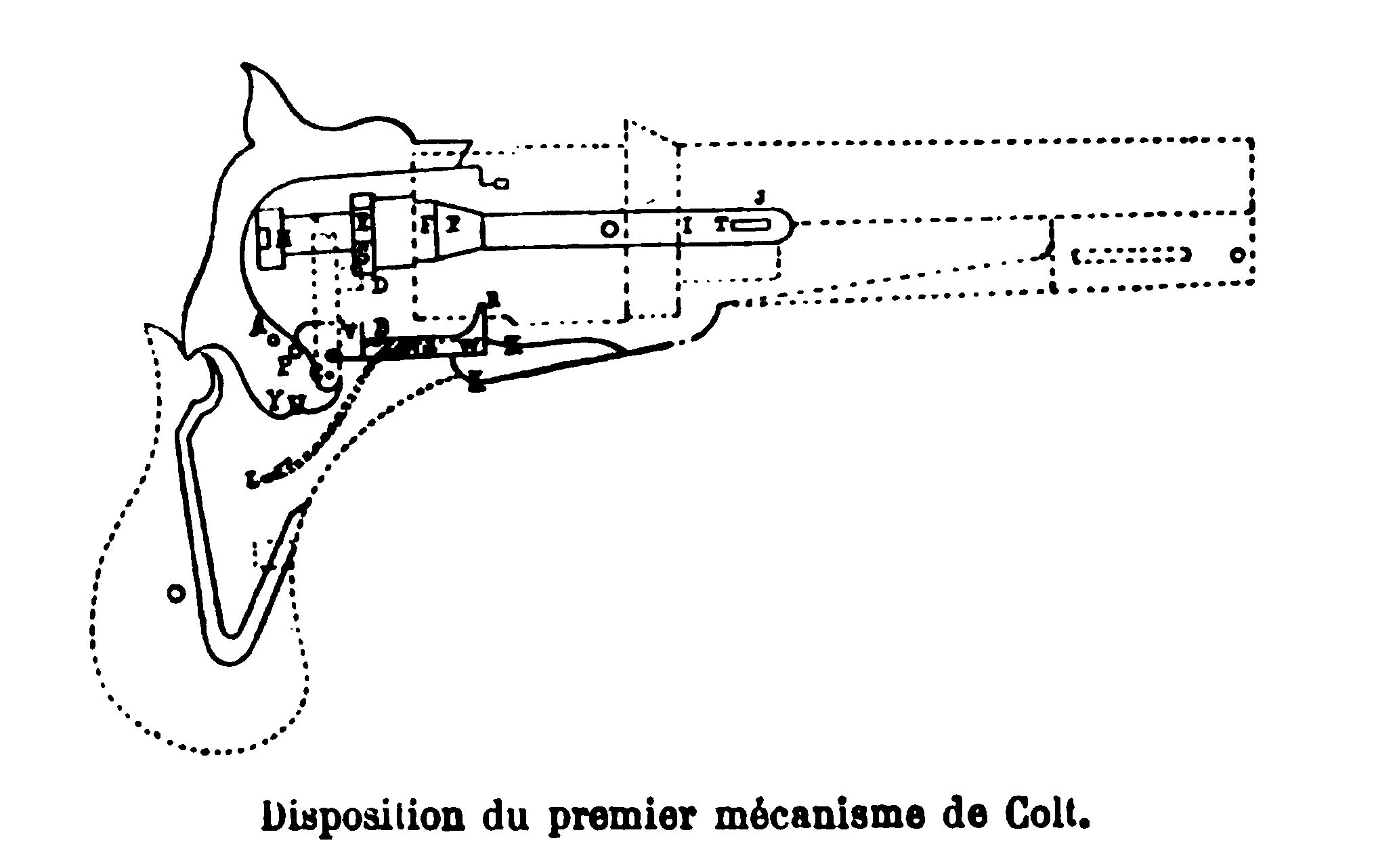
The battery is mounted on pin A. The key or ratchet lever that retains the cylinder is mounted on pin B. The lifter intended to move the ratchet is, by a mechanism, in relation to the battery on the left side, at point C. Arm D of the lifter engages in the teeth of the ratchet on the right. E represents the ratchet when it is in contact with the chain. FF are the middle and front parts of the chain or rod on which the ratchet is placed. G is the shaft on which the cylinder turns; end E is the nut that holds the shaft in place. I represents the front end of the shaft that passes through the plate and its projection on the lower part of the barrel, and the barrel is attached to the shaft by a key at point J. K represents the pin of the trigger. L is the spring that pushes the connecting rod against the end of the battery. M is the spring that pushes the key that retains the cylinder.
O is the main spring. By pulling back the battery hammer, pin Q acts on the rear end of the key or ratchet lever that tightens the cylinder and lifts it; consequently, the other end R is moved away from the cylinder, and arm D of the lifter begins to act on the tooth S on the ratchet side, which, being in contact with the cylinder by means of the chain, turns until the nearest chamber is brought into alignment with the barrel. When pin P is moved away from the key by passing over its upper end T, the pin presses end R of the key by means of spring M into the next stop of the cylinder: at the same time, by the action of the lower end of the battery hammer U on the connecting rod V, a horizontal forward movement of the rod is produced when end W is brought into contact with the upper projection of the trigger, and the trigger is brought to the proper position for the finger when the clip X of the trigger engages the connecting rod that holds the battery hammer when it is cocked or at rest by means of end V, which enters the lower latch Y of the hammer. By pressing the trigger to discharge the pistol, the connecting rod is detached from the hammer latch, the main spring pushes the hammer forward, and its upper end strikes the primer cap; during this operation, the lifter, by its lateral movement to the left, falls on the next lower tooth of the ratchet: by the lateral movement of the rear end R of the key that retains the cylinder, pin P of the battery hammer falls again under this key. By repeating this same movement of the battery, the same effect is produced until, successively, each chamber of the breech is brought in turn into alignment with the barrel and discharged. (a)
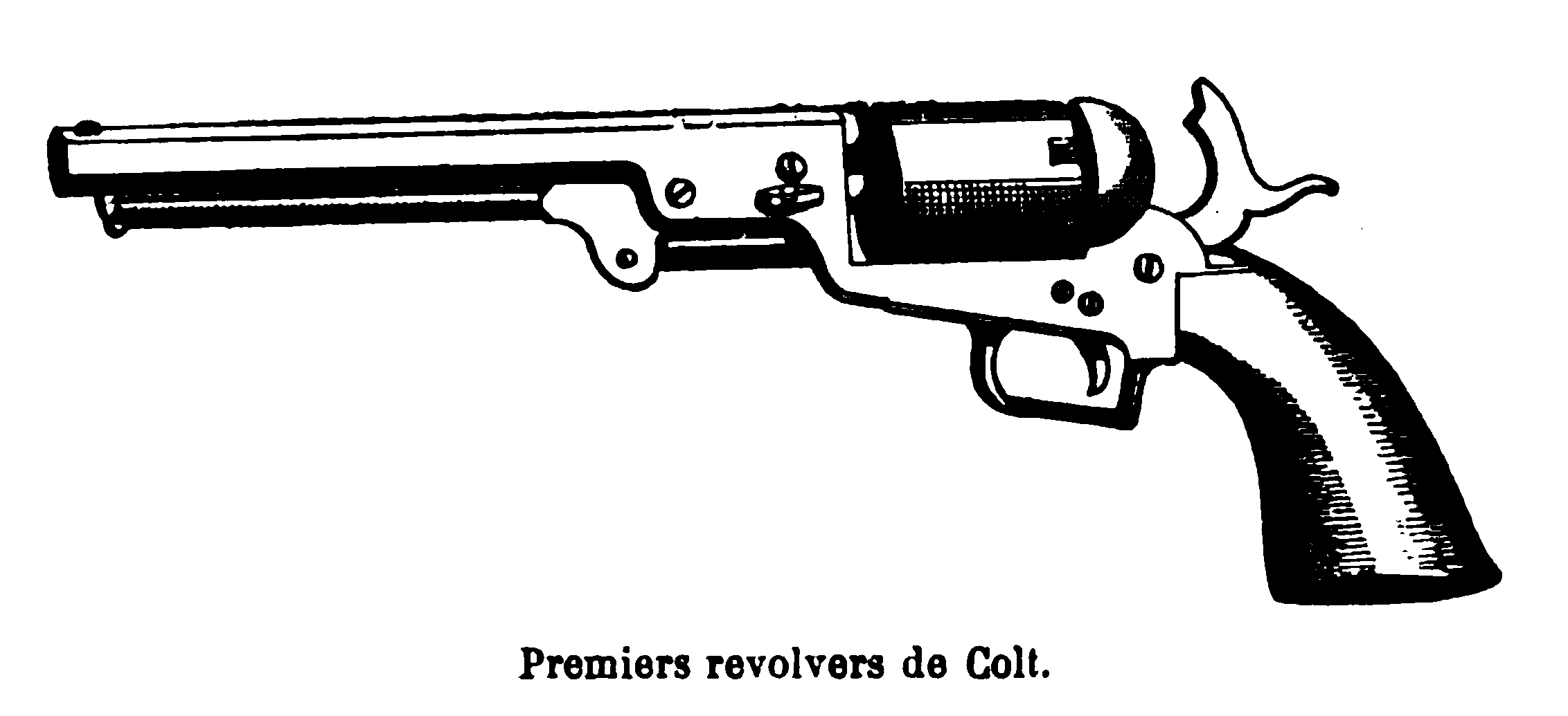
Since then, Colt has gradually perfected his revolver, which consists of a single, fixed barrel meeting at its rear end a cylinder drilled with six parallel tubes rotating smoothly around an axis.
Each of these tubes is closed at the rear by a chamber bearing a chimney on which a cap is placed; the cylinder has on its outer face a six-notch ratchet that turns by a sixth of a circumference by means of a piece articulated with the hammer and which moves when cocking the latter; to load each of the revolver’s chambers, powder is placed by hand, then a bullet is forced with a rod moved by a toggle lever straightened along the barrel when not in use.
The unloading of a chamber, in case of a misfire, presents great difficulties; the forced bullet in the cylinder must be removed in pieces; there is still some inconvenience in placing the caps; since the chimney carrying them is separated from its neighbor by a strong protrusion intended to prevent the ignition from spreading from one to the other, if one’s fingers are numb or wearing gloves, it is difficult to insert the cap and fix it on the chimney.
As it is, however, Colt’s revolver marks a significant epoch in weapon construction and in the history of civilization; it has played and still plays a very important role in the armament of North Americans, and in the form of revolver carbines as well as pistols, it has been one of the leading figures in the Civil War.
On the other side of the Atlantic, this universal panacea intervenes constantly in public and private life, but on the old continent, it is not yet generally adopted in the armament of regular armies. It is not in the direction of repetition but towards quick and easy loading that European gunsmiths had directed their work.
Mr. Perrin had indeed manufactured a six-barrel pistol grouped around a central axis, but it turned by hand and was little spread. In 1842, Mr. Devisme made a carbine with six small juxtaposed barrels discharging into a single barrel: in each of them, from the rear part, small cylindrical steel blocks carrying the charge on their front face and the cap on their outer face were inserted; this cap was carried on a central chimney and ignited by the percussion of a small cylindrical piece sliding under the hammer’s impact. This carbine, although very ingenious, did not spread more than the Perrin and Lenormant pistols.
There were also Hermann and Mariette, who did not achieve celebrity. Only Adams of Adams and Deane seriously competed with Colt.
The Belgian gunsmiths, so skilled and always ready to seize an industrial idea, seeing the success of the Colt revolver, were also led to manufacture revolvers; some of them, recognizing the flaws in the American colonel’s weapon, sought to substitute various combinations.
Mr. Hartoy and Mr. Devos, in 1853, and Mr. Malherbes and Mr. Rissak, some time later, composed revolvers using Flobert cartridges. But the revolver, solid, easy to load and unload, assemble and disassemble, and simply built enough to be put in the hands of soldiers, was yet to be created. Indeed, the American pistol, those of Adams, and those of Mangeot-Comblain of Brussels did not produce entirely satisfactory results; too meticulous care was needed to fix the powder at the bottom of the chambers by forcing the bullet, and for cavalry, where pistols placed in holsters are mouth down, the charge was too exposed to displacement and even to falling, and the danger of accidental ignition by communication was not sufficiently eliminated.
The revolvers manufactured by Mr. Lefaucheux in recent times no longer carry the vertical pinfire cartridge; it was recognized that, especially for the revolver, it was less perfect in use than the central-fire cartridge, which has reached the degree of perfection it has today. The weapon consisted of a single-piece drilled and forged iron barrel with a perpendicular part to its axis that was screwed at a right angle to the rest of the frame, in front of the trigger and below the lower level of the cylinder; this frame, extending horizontally to receive and carry the trigger parts, rose at a right angle parallel to the perpendicular piece to the barrel’s axis and thus formed a square housing, open at the top, where the cylinder carrying the chambers was placed, the rotation of which took place around a rod parallel to the barrel’s axis, fixed at the rear in the breech and passing through a piece called the nose, attached to the barrel; the hammer passed through a notch in the breech and struck, at the center of the base of the cartridge, a cap inserted in a chamber and carrying an anvil inside to ignite the fulminate. All the battery parts were attached to the lower and rear part of the frame and almost entirely hidden under the wood of the weapon.
This revolver had some drawbacks in its somewhat shortened form, which did not give enough play to the trigger and did not allow large gloved hands, for example, of gendarmes or cavalry, to easily move the trigger. The rod did not adhere well enough to the barrel and could catch on passage; the barrel carried by the nose was only connected to the frame by a screw, and, being cantilevered, was exposed to bending if dropped. Other purely manufacturing considerations led Mr. Lefaucheux to modify this revolver and adopt the current model described below:
The frame is cast in one piece from very resistant cast iron; it consists, from back to front, of a plate about three millimeters thick, absolutely flat on the right side and hollowed out on the left, leaving a protruding edge to form a sort of flat chamber; it ends in a bulge forming the cap in the middle of which a hole receives the rod of the ring that serves to suspend the weapon; this plate exactly outlines the shape of the pistol grip, which will later be covered by the wood.
Continuing from back to front, the frame thickens on the right to support various parts, and rises to about two centimeters thick to form the breech; this breech presents a slot at the rear in which the hammer moves, it widens to the left in a shell shape to cover the interior face of the rotating cylinder and protect the cartridges placed in the chambers; it is notched on the right to receive the door through which the cartridges are placed, and which, once closed, extends the shell and fulfills the same protective purpose for the cartridges on the right side.
At its front part, the breech has a small slot for the movement of the notch whose tip lifts the edge of the ratchet serving to move the cylinder of the revolver, it also has the hole in which the axle serving as the axis will be inserted.
After rising six centimeters to thus form the breech, the frame bends at a right angle and extends horizontally from back to front for five centimeters, at the end of which it swells to support the barrel, the front axle hole, and the rod passage hole; it descends to meet at a right angle the lower part also advancing at a right angle from the base of the breech and carrying at its rear face the trigger, the trigger guard, and the guard.
Thus, instead of drawing an open frame at the top, the front part of the frame now forms a complete frame cast in one piece, without screws and without joints, which no longer offers any point of rupture or misalignment. This frame is cast in core molds, and when it comes out of the sand, it already has its well-defined shape, its slots, and some of its holes.
One begins by drilling in the solid part at the front and upper part of the frame a hole to house the barrel, and with a threading machine, the nut thread is traced in this hole, which will receive the threaded part at the rear end of the barrel; on the same machine, by moving the frame in a slide, the axle hole is centered; using a punch mounted on a cutting lever, the slot for the notch already indicated by casting on the inner face of the breech is opened; with a toothed milling cutter, the slot for the hammer housing already also indicated on the piece when it comes out of the mold is refined; with another milling cutter, the four inner faces of the frame are planed.
The frame is fixed in a completely closed box on which are indicated the holes to be made in the frame to house the various screws that will fix the mechanism.
This is the same process we saw used in clock-making at MM. Japy’s to accurately drill in the plates of watches and clocks the pivot holes that must all be mathematically calculated distances. Thus, this matrix containing the frame is brought before a drilling machine equipped with drills of various sizes to successively drill the front holes in the box containing the frame to make, moving from front to back, the screw hole for the pin spring, the screw hole for the door spring, the trigger screw hole, the hammer screw hole, the screw hole fixing the trigger guard to the sub-guard, the two holes for the wood screws, and, at the very back, the screw hole for the main spring.
When these holes are fixed on the flat part, the box containing the frame is raised, it is presented vertically to the drill that pierces the rod passage hole. As for the hole at the very rear of the rear plate of the frame, through which the nut fixing the suspension ring rod can be moved, it was cast, only its edges are bored. It remains only to drill, at the upper posterior angle of the cage, the hole through which the hammer operates the percussion so that the frame only needs to be polished before being assembled with the other parts of the weapon.
The cylinder, three centimeters high and four in diameter, is cut from round steel bars from MM. Petin and Gaudet; a lathe with a stand pierced with a hole in which the bar is engaged is used to successively advance the bar towards the chisel as each piece is cut off; the chisel, carried on a carriage, is gradually advanced to cut the bar circularly to about one centimeter from the central part of the steel for the front face of the cylinder and one and a half centimeters for the rear face. When two protrusions have been provided in the middle of each of its flat faces, it is cut off at a height of a few millimeters from the part left by the chisel; thus, a cylindrical steel piece bearing a protrusion in the middle of each of its flat faces detaches. This block is drilled through the center to create the axle hole, then bored, the circumference is then turned, and the two vertical faces are planed.
The cylinder is threaded onto a rod rising in the middle of a plate placed under a drilling machine, above the cylinder a counter-plate or guide pierced with six holes is driven in. When the counter-plate is fixed, the whole apparatus can be turned and each of the six guide holes presented to the drill successively. The drill descends and marks the holes to a depth of five millimeters. The operation is not continued with the guide plates, but the started drillings are finished on an ordinary drilling machine.
These chamber holes are not uniform throughout their length; they have a slight protrusion about one centimeter from the front opening, so their diameter is slightly narrower in this part than in the rear part forming a chamber, where the copper cartridge is placed: the bullet engaged in this narrower part of the chamber undergoes initial swaging before engaging in the barrel. This way, the chances of wedging or cutting the lead bullet on the long barrel’s edge are reduced, as the juxtaposition with the cylinder is not hermetically tight, for if the fit were too tight, the rotation would not operate as easily.
Completely at the rear of the chamber, at the mouth of the chambers on the rear face, a groove is hollowed out to house the washer forming the cartridge base and which must prevent the backward return of the powder gases; this washer must disappear completely under the groove; otherwise, the cylinder’s rotation would be hindered at the rear. When turning the cylinder’s circumference, the two front centimeters are hollowed out by one or two millimeters more, and the rear centimeter is left protruding, in which the notches to be stopped by the small protrusion coming out at the frame’s base when the trigger is pulled back are hollowed out. On the front face, the ring that must receive the axle at the front is milled and adjusted; on the rear face, the median protrusion is divided into six inclined plane notches, together forming the ratchet to be pushed by the pin that determines the rotation. The cylinder is then sent for polishing.
The barrel is cut from a steel bar to a length of fifteen and a half centimeters, it is drilled vertically in a machine where the barrel, centered by four screws in a vice, pivots on itself, while the drill remains fixed. This drilling is done in one pass; it is rapid enough to drill ten barrels on a single machine in an hour. The boring is done with a square bit, with wooden wedges, like boring rifle barrels; the drilled and bored barrel is mounted on a lathe and turned to its thickness by a chisel, making it slightly conical from back to front, which slightly reduces the weapon’s weight and gives it a certain elegance while maintaining strength where it is needed. The interior surface has four grooves cut by machine to a depth of three-tenths of a millimeter, with a pitch of 1′ 20; the sight and the rod slide are soldered and brazed, then the barrel is sent outside the factory to special workshops for polishing with the other parts. The trigger guard and its bridge are also polished. This polishing is done on a wooden wheel covered with buffalo, with emery for the first passes and England rouge for the final ones.
Upon return from polishing, these exposed parts of the revolver would be exposed to rust from air contact in stores as well as during travel or campaign, so they must be protected by dipping their surface. The cylinder and the barrel are placed in a bed of baker’s ash and heated until they reach a persistent blue; from time to time, the pieces are removed from the ash and wiped to prevent grime deposits from forming on the surface.
The frame and the hammer are tempered differently because it is customary to give their surface the sought-after agate-jasper color, corresponding to a particular metal state that makes it non-oxidizable and of such a hard grain that if not annealed, even the sharpest file would not bite into it. This jasper is obtained by laying the pieces in tin chests on a bed of calcined and fragmented sheep bones and covering them with similar fragments so that each piece is surrounded on all sides: bones from another animal do not give an identical result.
These sheep bone fragments, after calcination, are black inside, white-veined gray outside, which is the result of incomplete calcination. After a passage through the oven and sudden immersion in a water tank, all parts of the metal surface that were in contact with the bone’s black are dark brown, all those juxtaposed with the white parts are light brown-gray, the others reproduce from light to dark the same jasper seen on the bone surfaces they were placed next to. After this operation, the polish is fixed, and the metal surface can fearlessly withstand oxidation; only assembling the cylinder, the trigger guard, and the frame with the barrel, wood, and battery parts remains.
The wood consists of two walnut plates of unequal shape and size; the right plate is simply the exact covering applied to the right side of the frame handle; it is pierced with two holes surrounded by escutcheon, called eyes. The left plate is thick and hollowed out to form a box to house the main spring and the base to which it is screwed between it and the left side of the metal handle; at the front, a small square cavity protects the hammer tail; it is also pierced with two eyes through which pass the screws that, crossing the frame’s tail and the right plate, connect these three pieces and form the battery box. The mechanism of the latter is as simple as it is ingenious; its function is not limited to moving the trigger, whose escapement releases the hammer; the series of movements is more complicated, and yet the entire mechanism consists of only five parts, excluding the main spring. These five parts are: the hammer and its chain, the trigger, the notch, plus two bars; one, the connecting bar of the trigger to the hammer, the other, the hammer stop bar.
The hammer differs from the piece thus named in percussion rifles in that it ends with a pointed steel cone, instead of having a flat surface at the tip; its tail is attached by a small chain to the main spring’s end, whose mission is to pull this chain up to tilt the hammer and its front part; it has a protrusion corresponding to an indentation in the small piece called the bar, which attaches it to the trigger; this bar is fixed to the trigger by the notch pivot.
The notch is a piece that the trigger’s tilting movement raises, and since its tip bears on one of the ratchet protrusions, lifting it raises this notch and, consequently, turns the cylinder. The trigger has attached to its rear angle the stop bar with two notches, one at the end, the other in the middle.
Here is how these parts interact: if, by putting your finger on the trigger, you pull it back, the notch turns the ratchet, the stop bar P rises at the same time and no longer holds the hammer’s tail fixed, which lowers while its head rises, the connecting bar Q tilts up and down until an edge of the hammer’s tail engages in the first notch at its end. The hammer is then, so to speak, in the safety notch. If you continue to press the bar and pull it back, the hammer tail passes over the second notch; the bar then returns to being horizontal, but this time from top to bottom and from front to back; with the main spring action becoming free, it sharply brings back the hammer’s tail, whose beak strikes the cap.
If you stop pressing the trigger when the hammer falls, you see all the parts return to their place; the trigger is brought down by the N spring, which lifts its nose and makes it tilt around the O screw, the notch goes down to lodge its beak in one of the ratchet notches again, and the stop bar becomes oblique from bottom to top again.
Each part is brought back to its place by the action of a small spring that is specific to it; thus the R spring pushes the hammer stop bar and applies it to the base of the hammer’s tail again. The T’ spring simultaneously presses the S bar towards the ratchet, and the connecting bar P towards the hammer’s protrusion.
If one wants to arm the pistol with the thumb without using the ability to arm it with the trigger, the parts play in reverse: thus it is the hammer’s tilting that lifts the trigger by the connecting bar P, which tilts the stop bar first to the safety notch, then to the arming notch; at the same time, since the connecting bar is connected to the notch by its pivot, it raises this notch, which acts on the ratchet and turns the cylinder. Thus, the pistol can be cocked either with the trigger or the thumb, depending on the need of the moment; the latter method naturally allows for more accurate aiming; when arming with the trigger, it is evident that since the rearward stroke is longer and the escapement only occurs at the end of this stroke, people accustomed to ordinary rifles and pistols are initially surprised by the length of the trigger stroke: indeed, in ordinary pistols and especially in target pistols, simply displacing the trigger from the vertical is enough to fire; here, the trigger must describe an angle of about 30 degrees to reach the escapement; the spring is also much harder, the effect is much greater than in ordinary weapons, but this is due to the multiple movements that the finger’s action makes perform.
The cartridge consists of a long copper base to which a cylindrical-conical bullet, hollowed at its outer part, is crimped; the powder fills the cavity between the bullet and some pieces placed at the bottom of the base, which we must list for those who did not read the previous delivery describing Mr. Gevelot’s factory. In the center of a small cardboard cylinder forcefully pushed and compressed at the base of the base, a copper chamber pierced with a hole, entirely covered by powder inside, has been introduced; a primer is lodged in this chamber, the opening forward, into which a small piece of brass has been placed; at the very rear and fixed to the base by the chamber’s vigorously crimped claws is a brass washer whose protruding edge acts as a seal during detonation.
When the hammer releases and is launched forward by the spring’s action, it passes through the hole in the breech, its point strikes the rear of the copper primer chamber, compresses it and the fulminate on the small brass piece inside that serves as an anvil. After firing, the cartridge shells fall out very easily by themselves, and if any stubborn bases refuse to come out, the rod’s action would expel them: such is the latest combination executed by Mr. Lefaucheux, which will address almost all objections raised against the use of revolvers as ordinance weapons.
Only one objection remains, that a small amount of gas escapes through the gap between the barrel and the chamber, and the weapon quickly becomes fouled; this defect seems inherent to the revolver, and since it is extremely easy to disassemble and clean, this slight defect is offset by so many and such precious advantages that it should not be a serious obstacle. The Ministry of the Navy understood this since it has just placed a significant order for pistols of this model with Mr. Lefaucheux.
At this moment, the factory is occupied with other tasks, as it delivers every day to the army four hundred rifles it has transformed into breech-loading weapons; the inventor of this transformation imitated the Schnider carbine, and, in our opinion, rendered a great service by finding a way to use old rifles with relatively low expense and very timely speed.
It involves simply cutting the barrel at the chamber and replacing the internal breech closure with an external piece forming the lower half of a chamber filled by a valve sealing the breech. This lower canal is fixed to the rifle’s stock, which is hollowed out to facilitate the placement of the charge. The valve moves on a chimney supported by a steel spring; it has been made very solid and very thick as a precaution, which makes the rifle a bit heavy.
The valve is drilled with an oblique canal housing a conical striker held by a steel spring; the entire battery and the old hammer have been retained, only it must be bent towards the middle of the weapon to strike the striker’s head.
At the moment of percussion, the cone sinks into the canal, protrudes into the valve’s inner face, and strikes the cap in a central copper chamber enclosed at the base of the cartridge’s base.
This transformed weapon was initially little favored; it is a bit heavy, less elegant than the famous Chassepot, and unfortunately, the first hastily manufactured specimens contained defective parts; thus, the striker, instead of being made of choice steel, was made of inferior metal, it broke under the shock, and the weapon, unable to open, became unusable, and the cartridges sometimes hastily made did not have all the desired perfection. The major objection from proponents of the new small-caliber projectile theory was that by retaining the large-diameter barrel, the bullet’s volume provided less perfect shooting than that of recently invented weapons and increased the supply weight. We have seen these so-called snuffbox rifles and their cartridges experimented with, the maneuver seemed easy, very quick, and very safe to us, their solidity very great, and we believe that, in any case, it offers no danger to those who handle them.
Moreover, they have the advantage of carrying the bayonet with great solidity as before.
But this military transformation will one day cease, and Mr. Lefaucheux’s establishment will continue with the same activity its revolver manufacturing. Already, although in Paris, 3,200 revolving breech carbines and 130,000 pistols of all sizes of the same system have been manufactured. Mr. Lefaucheux has taken a patent in Belgium and defended his inventor’s rights with as much energy as in France; and rightly so, because in that country alone he has already stamped about 300,000 copies of his revolver made by Liège manufacturers who paid him a license fee.